Know about the Build Up Process of Flex PCB

Keywords: Flexible PCB, Flex Circuits Board
The rigid type is the most common type of Printed Circuit Boards, but another type that you may think of using it is the flex one after getting yourself familiar with.
Modern electronic gadgets, with the emergence of Flexible PCB technology, have come a long way. In the core of many delicate and sensitive electronic products, they are found. This technology is being used in even many electronic gadgets like your calculators, camera, Smartphone, and laptops.
Flexible PCB
From polyimide, it is made of a base substrate material. Both synthetically and naturally, this material is found and is used in various industries like clothing, automobile, etc. considerable weight, space, and savings is offered by the compact nature of high electrical-connection density and flexible circuits as compared to the traditional rigid printed circuit boards.
Build Up of Flex PCB
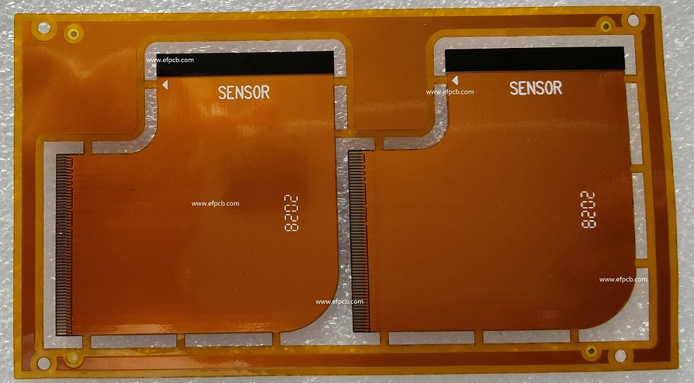
Base material saving is the main concern and this is the major phase. For the flex circuit, the primary material used is Polyimide. This material is expensive and must be used properly. You need to keep circuits close to each other for appropriate polyimide usage, as much as possible using the nesting technique. The following processes are involved in the prototype PCB manufacturing:
Sizing conductor: greatest flexibility is provided by it. Thus, particularly when you want to use the circuit for dynamic applications, you need to select the thinnest copper.
Looping: Addition beyond the designer's limit amount of extra material is acceptable. A service loop is this extra material that enables the Flex Circuits Board assembly and servicing length.
Routing: Conductors Routing of the can be easily done. To the fold and bend, simply get on the perpendicular position. By reducing stress, this will improve bending and folding.
Etching: for any isotropic losses, this process is done to compensate in the manufacturing process. The copper foil thickness is half the line width loss during this process. Several factors impact the conductor, different copper types, line width, etch mask, etc.
Ground Planes: If there is adequate electrical allocation, ground areas are created crosshatched. In improving the flexibility of the Flexible PCB circuit, this aids by decreasing the circuit board weight.


