Key Aspects of SMT Assembly Process for BGA Components
Keywords: BGA assembly
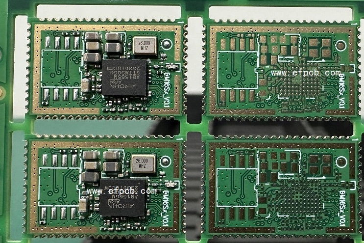
Along with the rapid growth of extremely large-scale integrated circuits (ICs), existing package types can never meet electronics assembly demands, and fresh packages emerge as a result of increased demand for greater integrity, lower board space, and larger I/O count. Among all of the newer forms of packages discussed above, the BGA (ball grid array) package is the major type with the broadest application areas because of its variety, which overcomes many constraints seen in older packages. In terms of soldering technology, the BGA package is quite similar to previous packages, such as the QFP (quad flat package). Nonetheless, pins are replaced with solder balls, resulting in a revolution in electronics assembly and the introduction of derivative packages such as CSP. BGA assembly soldering has been integrated with traditional SMT (surface mount technology) and can be carried out using standard SMT assembly equipment.
The Ball Grid Array (BGA) is a surface-mount packaging with solder ball connections beneath the component. BGAs have higher connector density than other packaging methods, however, they can be difficult to solder successfully in surface mount technology (SMT) assembly.
The use of BGA (ball grid array) significantly reduces assembly faults when SMT (surface mount technology) / SMD (surface mount device) practitioners discover QFP (quad flat package) with a pitch of 0.3mm incapable of achieving SMT quality accomplishment. According to system theory, reducing the difficulty level of process technology leads to problems being solved as quickly as possible and making product quality more easily controlled, which is consistent with the concept of modern manufacturing, even though BGA component inspection is difficult to implement. This blog will examine and analyze the SMT assembly method for BGA components in all directions using actual volume manufacturing.
Overview of BGA Packages
Pros
BGA components offer various advantages:
- More interconnections than perimeter-leaded components
- Smaller footprint than perimeter-led components
- Short connection lengths
- Protection for die and wire bonds.
Challenges
However, BGA soldering presents process problems
- Solder joints are buried below the container.
- Dense package footprint restricts Solder paste printing
- The thermal mass of big BGAs affects profiling.
- Sensitive to board warpage and coplanarity
- Robust BGA solder junctions need careful process control.
Key Features of the SMT Assembly Process for BGA Components
Pretreatment
Although certain BGA components are less susceptible to humidity, all components should be baked at 125°C since low-temperature baking has not been shown to have any harmful effects. That also works for bare PCBs (printed circuit boards) that are ready for SMT assembly. After all, moisture may be addressed first, resulting in fewer solder ball flaws and improved solderability.
Solder Paste Printing
According to my assembly expertise, solder paste printing is typically simple to execute on BGA components with a pitch greater than 0.8mm and QFP components with a pitch of 0.5mm. However, there may be situations when tin needs to be corrected manually because certain solder balls did not receive enough solder paste printing, resulting in soldering displacement or short circuits.
Nonetheless, it is not believed solder paste is easier to print on BGA components with a 0.8mm pitch than on QFP components with a 0.5mm pitch. It is believed that many engineers are aware of the difference between horizontal and vertical printing on QFP with a 0.5mm pitch, which can be explained mechanically. Thus, certain printers can print at 45 degrees. According to the idea that printing plays an important role in SMT assembly, adequate attention should be paid.
Placement and mounting
According to actual assembly experience, since physical qualities lead to high manufacturability, BGA components are easier to mount than QFP components with a 0.5mm pitch. However, the biggest issue we confront throughout the SMT assembly process is vibration on components when a large-scale nozzle with a rubber ring is utilized to position components on circuit boards larger than 30mm. Based on studies, it is considered that it occurs as a result of too much pressure within the nozzle owing to excessive mounting strength, and it may be eradicated with appropriate changes. BGA components have an obvious self-centering effect during the soldering process due to the surface tension of solder, so some designers purposefully enlarge pads on the four corners in BGA pad design to make the self-centering effect more obvious, ensuring BGA components can self-reset when mounting positions are shifted.
Soldering
Reflow soldering using hot air is an unusual procedure within the SMT assembly process, or it may be classified as a unique technology. Although BGA assembly components have an equal time and temperature curve to the standard curve, they differ from the bulk of conventional SMDs in terms of reflow soldering. Solder joints of BGA components are located beneath components, between the component body and the PCB, which means that BGA components are significantly more influenced by solder joints than typical SMDs, whose pins are located on the perimeter of the component body. At the very least, they are immediately exposed to heated air. Thermal resistance calculations and practices show that solder balls in the middle part of the BGA component body experience thermal delay, moderate temperature rise, and a low maximum temperature.
Inspection
Because of the physical architectures of BGA components, visual inspection cannot match the inspection needs of concealed solder connections, thus X-ray inspection is required to detect soldering defects for example, air holes, voids, short circuits, and missing solder balls.The sole downside of X-ray examination is its high cost.
Rework
BGA rework has grown in importance because of the widespread use of BGA components and the adoption of electronic goods for personal telephony. However, unlike QFP components, BGA components cannot be reused once they have been dismantled from the circuit board.
Now that BGA packaging technology has become the norm in SMT assembly, its technological complexity level must never be underestimated, and the major aspects discussed in this article should be thoroughly and accurately assessed, with concerns logically resolved. When picking an electronic contract manufacturer or assembler, look for a professional manufacturing line as well as full-scale assembly capabilities and equipment.
In the BGA assembly process, electrostatic protection and BGA component baking are additional factors to consider. BGA components typically require special containers that provide electrostatic protection. During the printed circuit board assembly process, stringent electrostatic protection measures should be implemented, including equipment grounding, staff management, and environmental administration.
Conclusion
To summarize, Ball Grid Array products offer significant connectivity density improvements but have unique soldering process problems. Quality BGA solder connections may be obtained by following the seven steps specified for precision printing, correct assembly, optimum reflow, resilient board design, handling controls, and comprehensive inspection. As sophisticated packages grow, further process innovation will be necessary to achieve acceptable yields and dependability. With many years of expertise managing PCB Assembly requests from global clients, EFPCB can solder practically any type of part onto circuit boards, including BGA assembly components. Among all of the newer forms of packages, the BGA (ball grid array) package is the major type with the broadest application areas because of its variety, which overcomes many constraints seen in older packages.
- 1Understanding UL 94V-0 Flammability Rating for Printed Circuit Boards (PCBs)
- 2Top 10 Flexible PCB Factories in 2025
- 3HDI PCB Market Outlook 2025: Future Prospects, Growth Analysis & Innovations
- 4HDI PCB Design Comprehensive Guide: Mastering High Density Interconnect Technology in 2025
- 5Top HDI PCB Manufacturers (2024)
- 6IC Substrate | Comprehensive Guide (2021)
- 7PCB core raw material CCL
- 8How to Make mSAP PCB?
- 9Top 10 IC Substrate Fabricators (2024)
- 10What is IPC 4761 Type VII Via in Pad PCB?

- Skype ID: shawnwang2006
- Phone No。: +86-755-23724206
- Email: sales@efpcb.com
- Quick Contact